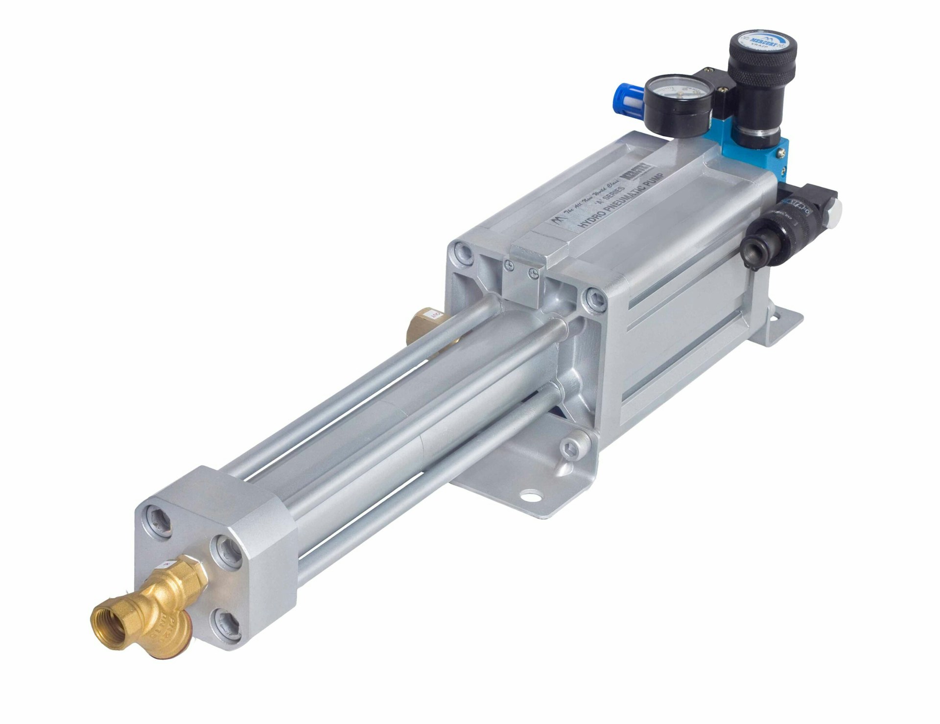
Pneumatic cylinders convert compressed air into linear motion and force. Proper sizing ensures your automation system performs reliably without being oversized (wasting air) or undersized (failing to move loads). This guide covers force calculations and cylinder selection.
The Basic Force Formula
Cylinder force depends on two factors: bore area and air pressure:
Force = Pressure × Area
For a circular bore:
F = P × (π × D²/4)
Where F is force in pounds, P is pressure in PSI, and D is bore diameter in inches.
Example Calculations
Extend Stroke Force
A 2" bore cylinder at 80 PSI:
Area = π × 2²/4 = 3.14 sq.in.
Force = 80 × 3.14 = 251 lbs
Retract Stroke Force
On retract, the rod reduces the effective area. For a 2" bore with 5/8" rod:
Rod Area = π × 0.625²/4 = 0.31 sq.in.
Effective Area = 3.14 - 0.31 = 2.83 sq.in.
Retract Force = 80 × 2.83 = 226 lbs
Calculate Cylinder Force and Size
Find the right bore diameter for your force requirement, or calculate force output at any pressure.
Standard Bore Sizes and Forces
Reference forces at 80 PSI shop air:
| Bore (in) | Area (sq.in) | Force @ 80 PSI |
|---|---|---|
| 3/4" | 0.44 | 35 lbs |
| 1" | 0.79 | 63 lbs |
| 1-1/2" | 1.77 | 141 lbs |
| 2" | 3.14 | 251 lbs |
| 2-1/2" | 4.91 | 393 lbs |
| 3" | 7.07 | 565 lbs |
| 4" | 12.57 | 1,005 lbs |
Sizing for Your Application
Never size a cylinder for exactly the required force. Apply safety factors:
- 25% minimum: For clean, horizontal, low-friction loads
- 50%: For vertical lifts or moderate friction
- 100%: For high-friction, dirty environments, or impact loads
If you need 200 lbs of force to move a load, select a cylinder capable of at least 250-300 lbs at your working pressure.
Pressure Considerations
- Shop air: Typically 80-100 PSI, assume 80 PSI for calculations
- Regulated pressure: Use the actual regulated value, not line pressure
- Pressure drop: Account for drops through valves, fittings, and long runs
Speed and Flow Requirements
Cylinder speed depends on air flow, not just pressure. To calculate required flow:
CFM = (Area × Stroke × Cycles per minute × 2) / 1728
The factor of 2 accounts for both extend and retract. Size valves and supply lines accordingly.
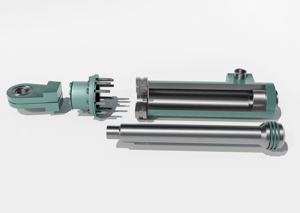
Mounting Considerations
- Fixed mount: For straight-line loads with minimal side thrust
- Pivot mount: For angular or articulating motion
- Guided cylinders: For precision applications or high side loads
Side loads on cylinder rods cause premature seal and bearing wear. Use external guides when side loads are unavoidable.
Common Mistakes
- Ignoring friction: Real-world loads include friction your calculation doesn't see
- Overlooking retract force: If you need force on both strokes, check both
- Undersized valves: A large cylinder with a small valve moves slowly
- No pressure regulation: Unregulated pressure causes inconsistent force and speed
Proper cylinder sizing balances force requirements, safety margins, and air consumption. When in doubt, going one size larger costs little in hardware but prevents frustrating performance issues in production.